
Geode Serial Port Pinouts and Functions
The Geode can come with a 9-pin RS-232C serial port. This allows the Geode to be mounted to a piece of equipment such as a tractor or a precision planter, or for connecting to a sensor such as a ground penetrating radar system (gprs). This type of configuration maintains a constant connection for data and power to the Geode. Use a straight-through 9-pin cable to establish communication at default 19200 baud rate between the Geode and your device. The functions of each pin are listed below.
Note: Be sure to use an RS-232 9-pin Sub-D Straight-Through (Extension) M-F serial cable. An M-M adapter with a NULL modem cable will not work.
You can remotely power on and off the Geode through pin 9 of the serial connection. Apply or remove +12V (nominal) to cycle power on the Geode. This link provides instructions on how to change the output baud rate of the RS-232 port. At all baud rates, the data coming out is 8-data bit, 1 stop with no parity (8-N-1).
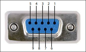
Pin | Signal | Condition |
|---|---|---|
1 | PPS output | Normally high, pulsing low |
2 | TXD out | +/-5.4V output |
3 | RXD in | +/-25V tolerant |
4 | Active high with rising edge synchronization (+/-25V tolerant)† | |
5 | GND |
|
6 | GPS Fix out | Active High, indicates a GPS fix |
7 |
|
|
8 | Speed Pulse out‡ | Normally low, pulsing high (+/-5.4V output) |
9 | +12V power input | Tolerance: 5–17VDC
|
*Pulse controls can be found in the Hemisphere GNSS Technical Reference Manual.
†Depending on the application, a GNSS solution may need to be forced and not synchronized with GPS time. Note: Event marker input is typical of most receivers but is not essential to normal receiver operation. Do not connect this pin if you do not need this function. The event marker input is max +/-25V (at least with the Hemisphere P34 in the GNS3) can be programmed as active low with falling edge synchronization (or optionally active high with rising edge synchronization). The input impedance and capacitance is higher than 10 k ohm and 10 pF respectively, with a threshold of lower than 0.7 V required to recognize the input. With the RS-232 transceiver in the Geode this IC is inverting the signal, so a high signal into the RS-232 pin 4 will turn into a low signal into the receiver. For details on the output, see Event Marker Input to Geode.
‡Speed Radar Pulse outputs a square wave with 50% duty cycle. The frequency of the square wave varies directly with speed.
93.99 Hz represents a speed of 1 m/s (3.28 ft/s) (Hemisphere Phantom 20/34 GNSS OEM Boards, Integrator Guide Revision: A3, August 18, 2021 pg. 48)
§Requires cable with 5.1 K pull-down resistor on either of the CC lines.