
GNSS/GPS Accuracy Explained
This article explains accuracy claims by various GNSS/GPS receiver manufacturers, including how to directly compare and evaluate those claims.
Accuracy and Precision
Over time, any stationary GNSS/GPS receiver will plot multiple positions for a given point. This happens because of errors caused by variables in the satellites, the surrounding physical environment, and the ionosphere.
Modern geospatial technology has made huge progress in correcting for those errors, but a receiver’s real-time accuracy is dependent on its ability to process those corrections. The points plotted by a stationary receiver eventually form a scatter plot like the ones below:
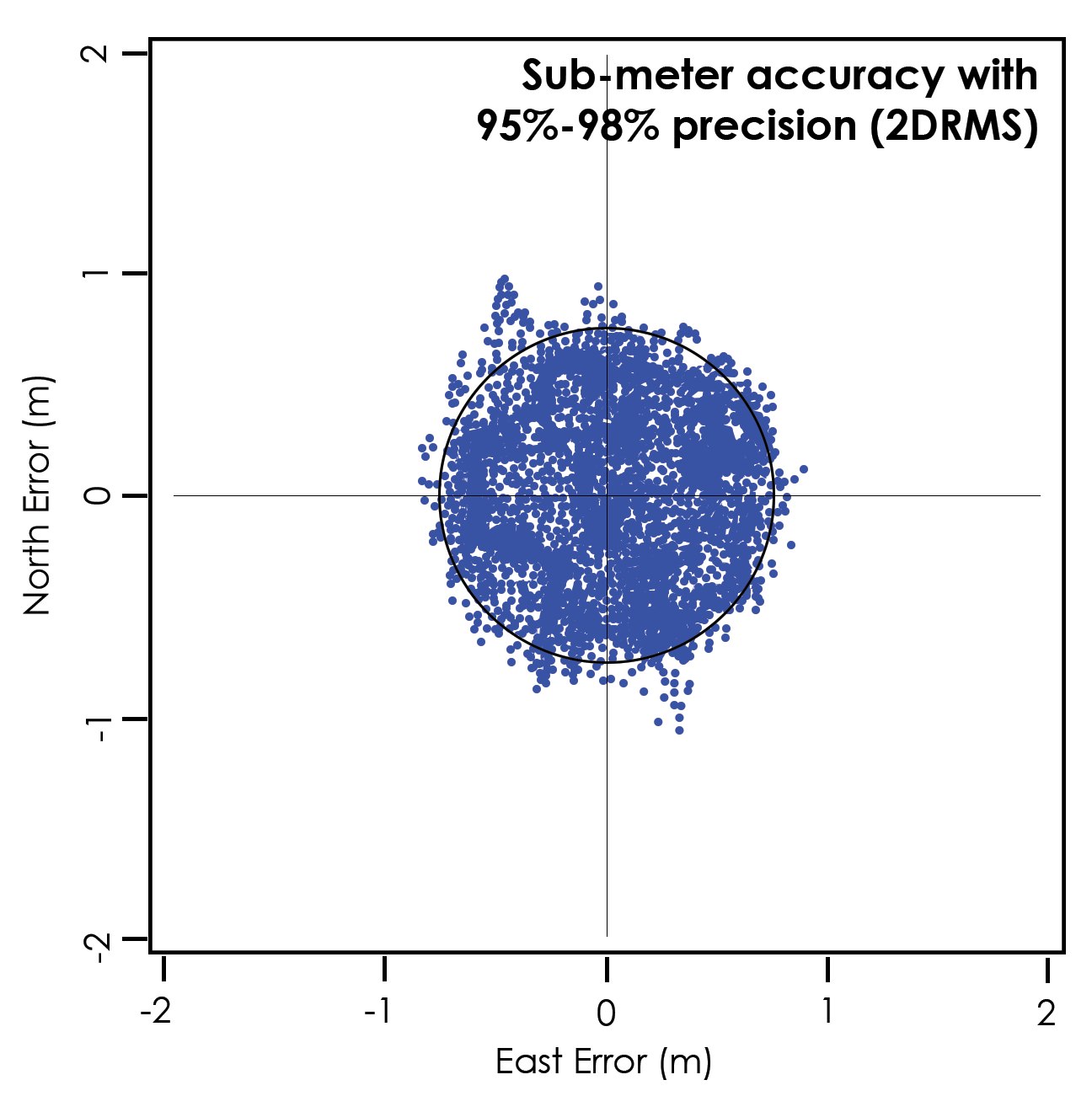
It is helpful to differentiate between accuracy and precision in these images.
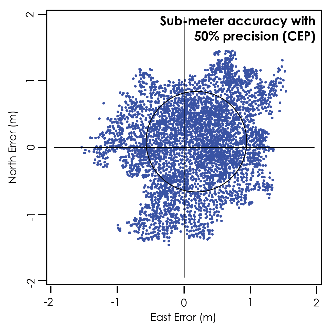
Accuracy refers to the radius of the circle of unknown around a true point. The smaller the radius, the higher the accuracy. A receiver with sub-meter accuracy can plot a position within a sub-meter radius of the true point. Both of the images above show sub-meter accuracy.
Precision refers to repeatability or how frequently a receiver can plot a point inside the circle of accuracy and whether or not that circle is centered over the true point. In the first image, the receiver has sub-meter accuracy with 95–98% precision. That is, 95–98% of the time, it will plot a point within one meter of the true point. In the second image, the receiver has sub-meter accuracy with 50% precision, i.e., the points fall within the meter radius 50% of the time.
Precision is calculated using industry-standard statistical analyses, shown in the table below:
Term | Definition | Precision |
|---|---|---|
CEP | Circular Error Probable | 50% |
RMS | Root Mean Square | 63-68% |
2DRMS | Two times the distance of RMS | 95-98% |
R95 | Radius 95% | 95% |
Published Horizontal Accuracy Statements
Manufacturers publish horizontal accuracy statements for GNSS/GPS receivers on product pages and in datasheets. Using the above table, you will be better able to compare both the accuracy and the precision of GNSS/GPS receivers.
For example, if the product page for a GPS receiver states a horizontal accuracy of 1 m 2DRMS, this means that during testing, 95–98% of data points collected with the receiver were found to be within a 1-meter radius of a true point. If another GPS receiver claims a horizontal accuracy of 1 m CEP, it is claiming that only 50% of test points were within the 1-meter radius.
The following table lists the published horizontal accuracy for the GPS/GNSS receivers used in Juniper Systems products:
Receiver | Published Horizontal Accuracy |
|---|---|
Spire GNSS Receiver |
|
Mesa 4 Windows (Quectel LC79H Dual Frequency GNSS receiver and integrated antenna) |
|
Geode GNS3 GNSS Receiver |
|
Mesa 3 Windows, Mesa 2 Windows, Allegro 3, Archer 3, Allegro 2, Archer 2 (u-Blox NEO M8) | Standard M8N and optional M8T
Optional M8T only
|
Geode Real-time Sub-meter GPS Receiver (Hemisphere OEM P206) |
|
Older Archer 2 and Allegro 2 (NVS NV08C-MCM) |
|
Archer (Hemisphere GPS XF101 and Crescent OEM P102) |
|
Original Archer (GlobalSAT BC-337) |
|
Mesa and AMXU pod (uBlox NEO 5Q and 6Q) |
|
IkeGPS |
|
*Atlas = Subscription required
*Autonomous = Using GNSS only for positioning (no correction)
*DGPS = Using GNSS with a correction source such as SBAS, WAAS, or EGNOS
Testing Criteria
Knowing the statistical method used to derive accuracy and precision still may not be enough to make a direct comparison between GNSS/GPS receivers. Testing criteria can also affect results. Manufacturers may compare test results to averaged coordinates of previously collected data points, certified surveyed horizontal and vertical coordinates of a physical marker (or just a vertical benchmark), or some other reference. It depends on the test criteria of the manufacturer.
The test criteria for the Hemisphere GNSS receivers (such as the OEM P206 Receiver in the Geode, or the XF101 Receiver for the original Archer) is found on page 7 of the Hemisphere GNSS Technical Reference Manual. Guidelines for evaluating the performance of a receiver are described starting on page 16 of the same manual.
Vertical Accuracy
Most receiver manufacturers do not provide a vertical (altitude/elevation or z-value) accuracy specification. Just as a general observation, the vertical accuracy of GNSS/GPS receivers is typically 1.7 times the horizontal accuracy. For example, a receiver with 1 m 2DRMS horizontal accuracy would likely provide closer to 2 m vertical accuracy. Again, this estimate is based on general observation of several different receivers, not thorough testing of any one receiver.
Location Information
When comparing location information from different sources (such as comparing a GPS receiver to a survey marker), it is important to account for the datum, coordinate system, projection, and other factors. The following web pages offer more details:
NSSDA Accuracy
The National Standard for Spatial Data Accuracy (NSSDA) is a standard guideline for measuring and reporting positional accuracy for maps and geospatial data. Developed by the United States federal government, NSSDA uses root-mean-square error (RMSE) to estimate positional accuracy. RMSE is the square root of the average of the set of squared differences between dataset coordinate values and coordinate values from an independent source of higher accuracy.
NSSDA is one in a series of five standards known as the Geospatial Positioning Accuracy Standards. This group of standards provides consistency in measuring and reporting geospatial data for different activities, such as geodetic surveying, topographic mapping, and facilities management mapping.
For more information, refer to the National Standard for Spatial Data Accuracy (Federal Geographic Data Committee Standard 007.3-1998).
More GPS Information
For more information about the accuracy of the US government’s Global Positioning System (GPS), visit GPS Accuracy.