Appendix A: Serial Port Configuration
The Geode has a 9-pin RS-232C serial port. This allows the Geode to be mounted to a piece of equipment such as a tractor or a precision planter. This type of configuration maintains a constant connection for data and power to the Geode. Use a straight-through 9-pin cable to establish communication between the Geode and your mobile device. The functions of each pin are listed below.
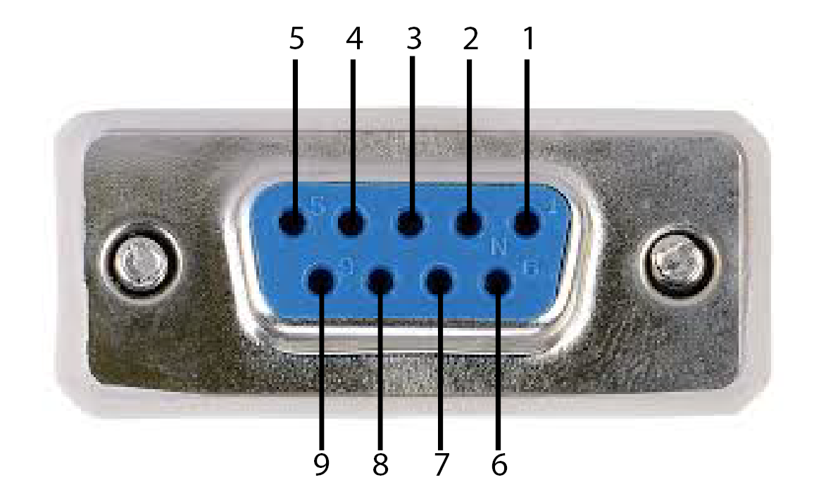
| Serial Port Configuration | ||
| Pin | Signal | Condition |
| 1 | PPS output | Normally low, pulsing high +/- 5.4 V, active low with falling edge synchronization |
| 2 | TXD out | +/- 5.4 V output |
| 3 | RXD in | +/- 25 V tolerant |
| 4 | Event Mkr in | Active high with rising edge synchronization (+/- 25 V tolerant) |
| 5 | GND | |
| 6 | GPS Lock out | Active high, indicates GPS fix |
| 7 | ||
| 8 | Speed Pulse out | Normally low, pulsing high (+/- 25 V tolerant) |
| 9 | +12 V power input RI (ring-in) signal |
Tolerance: 5-17 V DC Maximum: 15 W Ideal: 12 @ 1.25 A (such as, consumer vehicle battery) Possible: 5 V @ 3 A (such as, USB-C charging cable) |
*Requires a USB-C cable with 5.1 K pull-down resistor on either of the CC lines.
You can remotely power on and off the Geode through pin 9 of the serial connection. Apply or remove 12 V (nominal) to cycle power on the Geode.